The Tracked Robot Project 2010
Page 3
We left off with the motor assembly so now we need a place to mount it... the chassis. Your chassis may be wood, plastic, or some other material depending on what you have avaiable and your personal preferences. I am going to document the construction and evolution of my robot as I perform each step. This is an open source project... so it can be modified, changed, and evolved into something even better. Since I don't know exactly how you will design and build your tracked robot, I'll point out the tips and tricks used on mine to help guide you.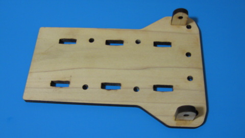
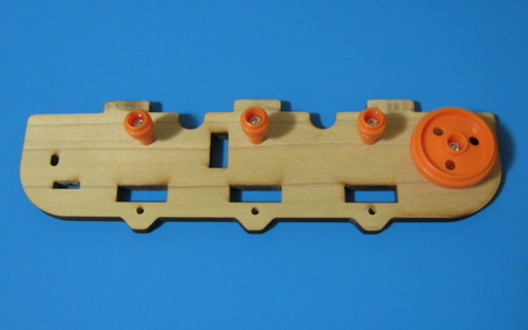
The first step is to glue the two tabs on which will hold the Infrared LEDs.
To
gauge how far the robot has traveled and to count the number of
rotations on each wheel some sort of sensor is needed. This design has
two 5mm holes to accept Infared (IR) LEDs which will shine light
through the matching holes in the wheels. This will then reach two
Infared Phototransistors inside the chassis where the pulses can then
be sent to the electronics to be counted. The tabs are the ONLY parts that get any glue on them.
Sand the surfaces with some 150 grit or 220 grit sandpaper to remove the laser cutting marks and make the model look better. The wood can be stained if desired while it is in individual peices. Once the surface is the way you like it, apply a small amount of white glue to the tabs and insert them as shown. Be sure they sit flush and square, then allow them to dry.
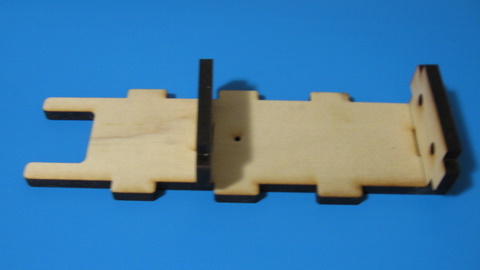
The center core with the two dividers.
Use
the supplied screws from the track kit to attach the parts as shown.
They should rotate freely when you are finished... if not, then back
off the screws about 1/4 turn until they rotate without binding. If
they bind it will effect how the track robot moves. The large diameter
wheel has three holes where the light from the sensor can shine
through. If you look through the hole in the wall plate, you should be
able to see through when the wheel is rotated. It may be required to
paint the inside of the wheel black to assist the sensor in working
better and avoiding stray light energy from getting through. You can
obtain plastic spray paint at any home improvement store or hobby
store. You can also use hobby paint... but DO NOT use airplane dope as it will melt the plastic!
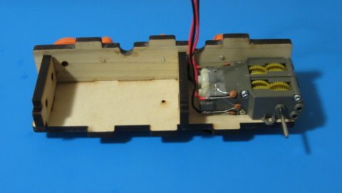
Motor assembly slid into position.
Sand the surfaces with some 150 grit or 220 grit sandpaper to remove the laser cutting marks and make the model look better. The wood can be stained if desired while it is in individual peices. Once the surface is the way you like it, apply a small amount of white glue to the tabs and insert them as shown. Be sure they sit flush and square, then allow them to dry.
The center core with the two dividers.
The two dividers sit into the center slots, do NOT glue them as they will NOT
sit against the bottom... they were designed to allow a bit of room
under them to allow a small gauge wire to be run if needed in your
design. One dividor has two 5mm holes where I may place some white LEDs
to act as headlights, or red LEDs to act as taillights... I haven't
decided yet if this is the front or the back!
Side with wheels attached.
Side with wheels attached.
Motor assembly slid into position.
The
motor assembly just slides into position with the shaft going through
the small diameter hole. There are two slots which accept the tabs on
the motor so no scres, glue, or any other method will be needed to
secure the motor. Once the motor is in place, it is time to attach the
opposite wall.
Both Walls installed.
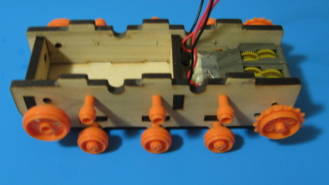
We are almost finished with the chassis build...
time to add the remaining wheels and axals to the chassis.
Once
the walls and wheels are in place the chassis is almost ready to roll.
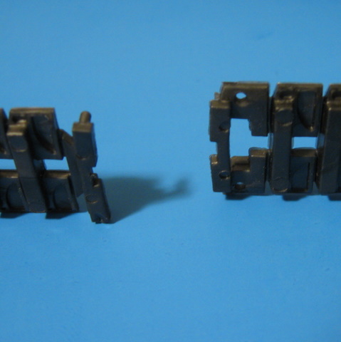
Next it is time to assemble the tracks and install them onto the wheels
to complete the drive train of the robot. The tracks come in several
peices which must be put together. The material is an artificial rubber
that has some stretch to it but not much. With my big fingers I found
it hard to put together... until I made a tool from a paperclip to hook
the tabs through the holes.
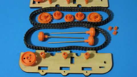
Tracks and parts ready for assembly
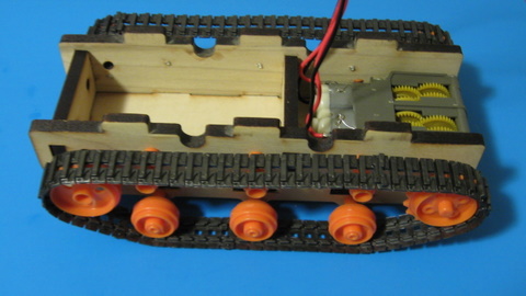
Tracks in place and ready to roll!
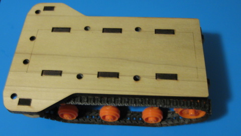
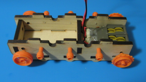
Chassis all assembled with top in place.
You will notice many holes in the top deck of the chassis, these are to run wires from the upper to the lower sections if needed. Since this robot is evolving as I build it... I wasn't sure exactly what I was going to install while designing the body in the CAD program.
Both Walls installed.
We are almost finished with the chassis build...
time to add the remaining wheels and axals to the chassis.
 Track Sections | 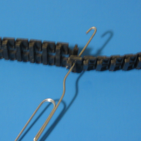 Push Hook Through | 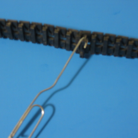 Pull Tabs Through |
Tracks and parts ready for assembly
Tracks in place and ready to roll!
Chassis all assembled with top in place.
You will notice many holes in the top deck of the chassis, these are to run wires from the upper to the lower sections if needed. Since this robot is evolving as I build it... I wasn't sure exactly what I was going to install while designing the body in the CAD program.