The Tracked Robot Project 2010
Page 4
We will be getting to the electronic brain of this robot in a little bit... the part that gives it the ability to avoid things, turn motors on and off... along with many other importan tasks such as blinking LEDs to look kool. But for the moment... let's look at two important components before we decide on a brain. Let's wire up the sensors to detect wheel rotations, and let's get a motor driver up and running so the brain can actually have a robot to control.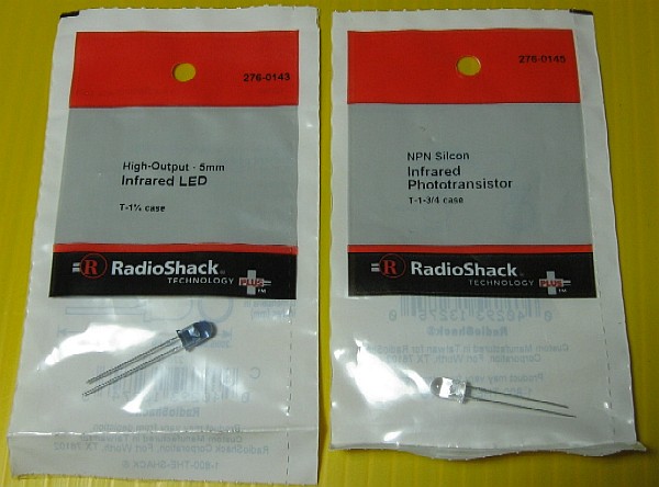
This is the basis for our wheel sensors... a very simple design.
Looking at the package, the IR LED (On the left) uses 1.2
volts at 100mA of current. I am going to run the robot from a 9v battery that I
am then going to regulate into a steady 5v supply. If we do the math... 5.0
volts - 1.2 volts = 3.8 volts more than the part can withstand. It would be
damaged but the higher voltage. We need to add a resistor... so we take the
voltage (3.8 volts) and divide it by the current (100mA) which can also be
looked at as 0.100 Amps.
I don't have a 38 ohm resistor as it is an odd value... but I do have some 39 ohm
resistors... what would that do? Let's find out...
So... the LED will glow 97% of its maximum intensity... I can live with that... and the LED will last longer at a lower current too. Actually... this is a great deal of current for a battery operated device, so likely we will experiment with increasing the resistance to drop the light output and current further. A normal LED runs about 20mA so this is almost FIVE TIMES the current. For now I am connecting a 2N2222 NPN transistor to the LED voltage supply. This will allow me to turn on the LED, make a reading, and then turn off the LED. If I run the LED only 1/10 of the time that alone could cut the power needed 90%. If I can also lower the current, I get additional energy savings, and the batteries last longer. At full load they would last about 3 hours. By being energy conscious I may be able to get 12 hours from a charge.
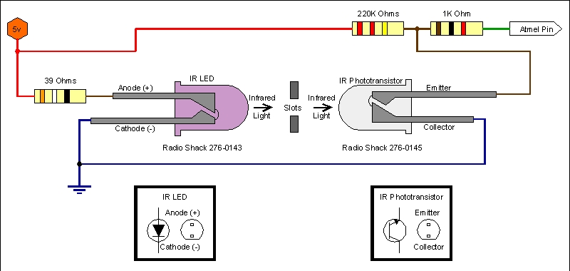
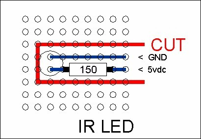
Here is the schematic working drawing of how the sensor gets wired.
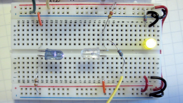
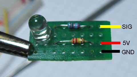
The circuit set up as a prototype on a breadboard.
The red traces are 5v, the blue are Ground.
The yellow wire at the bottom runs to an Atmel Mega 88P for testing.
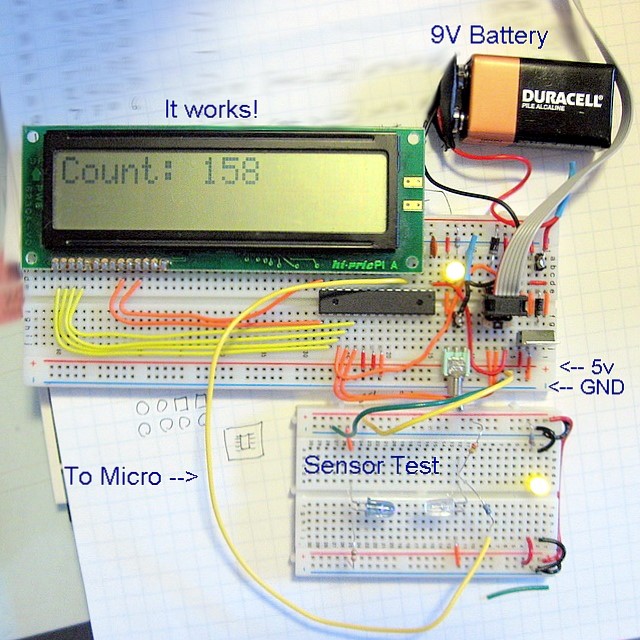
This is my test setup sitting on my messy desk.
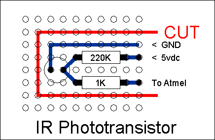
(View from SOLDER SIDE of board)
Simple Circuit Layout for the Phototransistor and resistors needed.
Circuit board cut to size |
Components installed, leads bent and cut to shape |
Solder applied to leads, wires not yet attached. |
Component side of board - wires not yet attached. |
Finished board showing connections to the main circuit board.
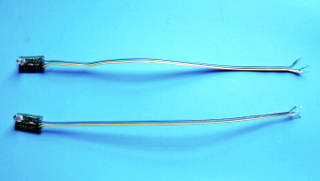 Sensors with wires installed, ready to mount. |
 Sensors mounted in the chassis. |
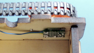
Mounted with a little bit of hot glue.
View from the SOLDER SIDE of the board.
The original testing was done using a 39 ohm resistor on the
LED board. This produced almost 100mA of current for each of the two LEDS, one
per side. This meant that a total of almost 200mA was being drawn from the
batteries when the LEDs were running. That's almost 1/4 amp... so the batteries
would run out in about 3 hours on a full charge. By increasing the resistance
we can lower the current... a typical LED runs about 20ma so these should be
able to operate between 20ma and 50ma. Let’s calculate the resistors for each
and experiment with the lower power setting.
Assuming 5 volts to the circuitry, we would use 1.2 volts for the LED and need
to compensate for 3.8 volts.
3.8 Volts divided by 0.020 amps ( or 20mA ) = 190 ohms
If we were to use a common 150 ohm resistor, that would give us 3.8 volts
divided by 150 ohms = 25mA (approx.)
I think 25mA is a good compromise... so that is the value we will use for
testing.
Video showing IR light beam on sensor