The Tracked Robot Project 2010
Page 6
Bringing it all together
We
have the breadboard mounted and the pin layout mapped out. Not it's
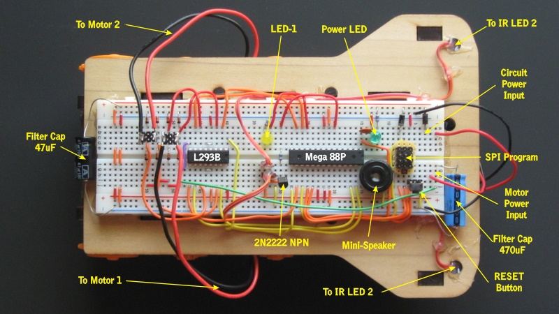
time to wire up the robot and begin bringing it to life. Here is a
photograph of the robot as I completed it at the time of this writing.
The motors are connected for testing WITHOUT the tracks installed. This
way I can run up the motors and test for overheating and other problems
without the robot rolling off the table. Once inital testing is
completed, the wires will be run more neatly and the tracks installed
for "road testing" to see how it handles on floors, carpet, grass, and
concrete.
Testing Configuration
Testing Configuration
As
you can see above, the bulk of the electronics is in place. The wheel
count sensors and the LCD need to be connected again but the robot is
capable of running under power and has run both motors forward and
reverse by setting the PWM pin to ON. This runs the motors at full
speed... which under 3 volts is rather slow... so we will upgrade to
4.5 volts to give it a bit more pep. By using PWM instead of just
turning the port to ON, we can control not only the direction but the
speed as well.
The motor driver uses three pins for each motor... or a total of six (6) pins for both motors. For each motor two of the pins set the direction to one of four states... IDLE, STOP, FORWARD, or REVERSE. The difference between IDLE and STOP is that in the IDLE mode the motors can free spin but in STOP the current generated by a spinning motor us used as a brake. Since this motor set is geared 203 to 1... there isn't much free spinning going on! The remaining pin will disable the motor when set LOW, and enable the motor when set HIGH. If you use PWM, the motor is actually switched on and off several hundred times per second... and if it is on more than it is off it goes faster. If it is off more than on... it goes slower.
Lets look at a few of the connections we have to the microprocessor and how they were developed for this project. Let's start with the LCD display that we are adding and that you will see in the images to follow. The LCD that we use is a character only type so it does not support commands like LINE, CIRCLE, etc. It is a very simple device to use in BASCOM... we simply define which pins are being connected to the processor, then we have a few simple commands that are available to us.
Once you have made the electrical connections, you need to tell the microprocessor how the chip is connected. We start off the BASCOM program by identifying the chip, some of it's parameters, and by telling it what is connected to it. The first lines 001 to 009 set up what type of processor we are writing for. If we didn't have these specified, we would need to use a drop-down menu each time to specify them. We have included this information with the special commands starting with the ( $ ) symbol. The software will now do this for us automatically each time we open the file and compile it. The lines in green that start with the ( ' ) character are remarks. A remark is just a note for you and I that the processor will ignore... it will not be loaded into the chip and it will not use any memory. So... ALWAYS put remarks in your code so that when you come back in six months... you will be able to figure out how it works again.
Starting at line 010 we tell the AVR that an LCD is attached and how to use it. First we let the processor know there are 16 characters and 2 lines of text available to us on line 011. We look at our connections and let the AVR know which pins are connected to what functions of the LCD in line 012. When that is finished, we can clear the display by using the command CLS, then place text onto the display with the LCD command.
The ports on the Atmel AVR series have three internal registers that we need to know about. There is a PORT which supplies signals to the outside world, a PIN which is an input from the outside world, and a DDR which selects between INPUT and OUTPUT modes. Since we want to connect our two switches to the Atmel physical pins 24 and 25, we need to remember how the chip is designed. Since the switch will be an INPUT, we need to assign them as PINC.1 and PINC.2 instead of PORTC.1 and PORTC.2 or we won't be able to read them. Once they are defined, we need to set the proper DDR to be an INPUT. There are several ways of doing this... but since you are just getting started with programming we will use the most simple method.
In our code we will include...
We could have also set all 8 of the bits at the same time... using a 0 for input and 1 for output... this is done by using a binary number. The binary numbers start with ( &B ) followed by the actual bits... larges to smallest. Since we are looking at setting pins 1 and 2... keep in mind the bits go from 7 through 0 reading left to right. Placing a 1 in all the other bits will leave them as an OUTPUT, the ones having a 0 will be the INPUTs.
Since you are already grasping enough new concepts... we will just stick with the first method for now. The second method will save some memory if you are defining a lot of pins however... so you may want to use it more as your code becomes more involved.
The motor driver uses three pins for each motor... or a total of six (6) pins for both motors. For each motor two of the pins set the direction to one of four states... IDLE, STOP, FORWARD, or REVERSE. The difference between IDLE and STOP is that in the IDLE mode the motors can free spin but in STOP the current generated by a spinning motor us used as a brake. Since this motor set is geared 203 to 1... there isn't much free spinning going on! The remaining pin will disable the motor when set LOW, and enable the motor when set HIGH. If you use PWM, the motor is actually switched on and off several hundred times per second... and if it is on more than it is off it goes faster. If it is off more than on... it goes slower.
Lets look at a few of the connections we have to the microprocessor and how they were developed for this project. Let's start with the LCD display that we are adding and that you will see in the images to follow. The LCD that we use is a character only type so it does not support commands like LINE, CIRCLE, etc. It is a very simple device to use in BASCOM... we simply define which pins are being connected to the processor, then we have a few simple commands that are available to us.
LCD Commands
- CLS - Clear the display and set the cursor to the first line and the first character.
- LCD - Display whatever text we want.
- Example: LCD "Hello World"
- The above would display "Hello World" on the LCD starting at line 1, character 1.
- LOCATE y,x - Place the cursor on line y at position x.
- Example: LOCATE 2,1
- The above would move the cursor to line 1 at position 2.
- CURSOR - This selects the type cursor, ON, OFF, BLINK
- Example: CURSOR OFF
- The above would turn the cursor off.
Connecting and Configuring the LCD
Connecting the LCD to the processor is pretty simple, the unit has 14 pins, connect pins 1, 3, and 5 to ground. Connect Pin 2 to your 5v supply. Once that's done there are two control lines called RS (pin-4) and E (pin-6) that get connected to an unused pin on the processor. There are 8 data pins starting at pin-7 to pin-14 but we are going to use only four of them. It is slightly slower... but we are not going to do more than 10 or 20 updates per second at most... so it's not a big deal. Here are the connections that were used in this project.| Connection | PIN | FUNCTION | DEVICE |
| GROUND | 1 | GROUND | LCD CHARACTER DISPLAY |
| 5 VOLT SUPPLY | 2 | VCC | |
| GROUND | 3 | CONTRAST (0 to 5 volts) | |
| Atmel AVR Pin 14 (PORTB.0) | 4 | RS | |
| GROUND | 5 | R/W | |
| Atmel AVR Pin 10 (PORTB.7) | 6 | E | |
| Not Used | 7 | DATA 0 | |
| Not Used | 8 | DATA 1 | |
| Not Used | 9 | DATA 2 | |
| Not Used | 10 | DATA 3 | |
| Atmel AVR Pin 17 (PORTB.3) | 11 | DATA 4 | |
| Atmel AVR Pin 18 (PORTB.4) | 12 | DATA 5 | |
| Atmel AVR Pin 19 (PORTB.5) | 13 | DATA 6 | |
| Atmel AVR Pin 06 (PORTB.6) | 14 | DATA 7 |
Once you have made the electrical connections, you need to tell the microprocessor how the chip is connected. We start off the BASCOM program by identifying the chip, some of it's parameters, and by telling it what is connected to it. The first lines 001 to 009 set up what type of processor we are writing for. If we didn't have these specified, we would need to use a drop-down menu each time to specify them. We have included this information with the special commands starting with the ( $ ) symbol. The software will now do this for us automatically each time we open the file and compile it. The lines in green that start with the ( ' ) character are remarks. A remark is just a note for you and I that the processor will ignore... it will not be loaded into the chip and it will not use any memory. So... ALWAYS put remarks in your code so that when you come back in six months... you will be able to figure out how it works again.
| LINE | BASCOM BASIC - Demo Program |
| 001 002 003 004 005 006 007 008 009 010 011 012 013 014 015 016 017 |
'=============================================================================================================== ' Tracked Robot Project 2010 - MEGA 88P Configuration - Written by Jerry Rutherford $regfile = "m88pdef.dat" ' At MEGA 88P <- Get this from the dropdown menu. $crystal = 8000000 ' 8MHz Divide by 8 off. <- Internal OSC for this chip from datasheet. $hwstack = 32 ' Default Hardware Stack <- Get this from the dropdown menu. $swstack = 8 ' Default Software Stack <- Get this from the dropdown menu. $framesize = 24 ' Default Frame Size <- Get this from the dropdown menu. $prog &HFF , &HE2 , &HDF , &HF9 ' 8MHz Internal, Divide by 8 OFF, PC6 = RESET <- Auto Generated. '=============================================================================================================== ' LCD Configuration Config Lcd = 16 * 2 Config Lcdpin = Pin , Rs = Portb.0 , E = Portb.7 , Db4 = Portb.3 , Db5 = Portb.4 , Db6 = Portb.5 , Db7 = Portb.6 '=============================================================================================================== CLS LCD "Robot Ok." '=============================================================================================================== ' More program stuff goes here.... |
Starting at line 010 we tell the AVR that an LCD is attached and how to use it. First we let the processor know there are 16 characters and 2 lines of text available to us on line 011. We look at our connections and let the AVR know which pins are connected to what functions of the LCD in line 012. When that is finished, we can clear the display by using the command CLS, then place text onto the display with the LCD command.
Switches A and B Theory
There are two switches installed on the robot to allow us to interact with the software. We can have the robot do something simple like displaying a message "Robot OK" on the LCD and flash an LED to let us know it is wating. This let's us know that the processor is working and that everyting should be okay to continue. Sometimes you don't want motors to start spinning right away... so we included two switches. One could have the robot do a simple test of the motors such as starting each one for a second or two just so that we know the batteries and motor drivers are all connected properly. The software could then jump to our main routines when we hit the second button. It allows us more control over how the robot behaves.The ports on the Atmel AVR series have three internal registers that we need to know about. There is a PORT which supplies signals to the outside world, a PIN which is an input from the outside world, and a DDR which selects between INPUT and OUTPUT modes. Since we want to connect our two switches to the Atmel physical pins 24 and 25, we need to remember how the chip is designed. Since the switch will be an INPUT, we need to assign them as PINC.1 and PINC.2 instead of PORTC.1 and PORTC.2 or we won't be able to read them. Once they are defined, we need to set the proper DDR to be an INPUT. There are several ways of doing this... but since you are just getting started with programming we will use the most simple method.
In our code we will include...
CONFIG PORTC.1 = INPUT
CONFIG PORTC.2 = INPUT
CONFIG PORTC.2 = INPUT
We could have also set all 8 of the bits at the same time... using a 0 for input and 1 for output... this is done by using a binary number. The binary numbers start with ( &B ) followed by the actual bits... larges to smallest. Since we are looking at setting pins 1 and 2... keep in mind the bits go from 7 through 0 reading left to right. Placing a 1 in all the other bits will leave them as an OUTPUT, the ones having a 0 will be the INPUTs.
DDRC = &B11111001
Since you are already grasping enough new concepts... we will just stick with the first method for now. The second method will save some memory if you are defining a lot of pins however... so you may want to use it more as your code becomes more involved.
Electrical Connection of Switches
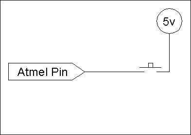 | You
might think that connecting a switch is as easy as soldering or
jumpering one end of the switch to the AVR pin, connecting the other
side to 5 volts or ground, and writing the program code. If you try doing that, you will get all sorts of unpredictable results when you try to read the switch. The reason is that when the switch is not closed (making contact) there is no reference to either power or ground. The signal can flucuate randomly and the processor will have no way to know if it is a valid signal or not. |
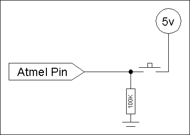 | One
thing we can do is to connect a resistor to ground, then connect the
switch between the atmel pin and the 5 volt supply. This is called a
bias resistor because it will cause the ARV pin to detect a ground
condition at all times except when the switch is closed and the voltage
then becomes 5 volts. You may also hear this referred to as a "steering
resistor" because it "steers" the voltage to a desired level. In this example the switch will detect a logic-0 until the button is pressed, then it will detect a logic-1. There is however a problem with this design. If the programmer sets the pin as an OUTPUT then tells it to become a logic-0 it will drop to a 0 volt condition. If the switch is pressed, the AVR will attempt to suck ALL the power down to 0 volts... and destroy the chip in the process. |
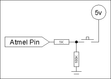 | If
we add a resistor in the path between the switch and the 5 volt supply,
then if the programmer makes the error above all that will happen is
that the chip will draw power through the resistor. This is a current
limiting resistor. If we do the math... 5 volts divided by 1000 ohms (1K) = 0.005 amps, or 5mA. Since the chip can safely draw up to 20mA per pin... we are well below this level and the chip is protected from poor programming. If the ground and the 5 volts were swapped in this example the switch would still work... it would show a logic-1 when NOT pressed and a logic-0 when pressed. This can be useful to know if you use a normally closed switch for example. |